
(:notabledit:)
Hardware | Papilio DUO - Papilio One - Papilio Pro - MegaWings - Wings - Shields
Contents
Overview
Specifications
Computing Shield SD-Card
Computing Shield VGA
Computing Shield Sound
Computing Shield Joystick
Computing Shield RS232 UART
Computing Shield Directional Butons
Computing Shield Led's
Computing Shield Keyboard and Mouse
Images
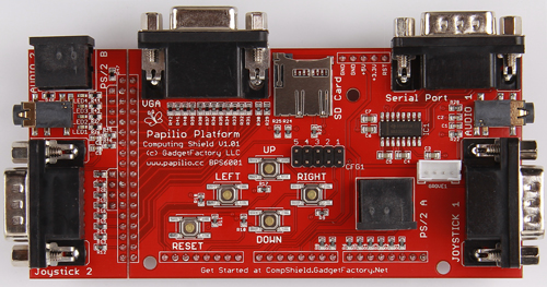
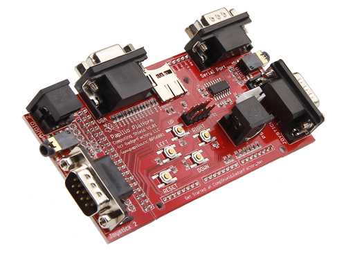
Computing Shield
The Computing Shield provides all of the hardware needed to recreate computing systems on the Papilio DUO.
Specifications
- VGA Port - 4r,4g,4b, 4096 Color, 12-bit VGA Output
- 2 Stereo Audio Jacks - 1/8" Stereo jack with low pass filter is ready for CD quality Delta-Sigma audio output.
- PS/2 Ports - Two PS/2 ports accept a keyboard and mouse.
- 2 Joystick Ports - Two DB9 Male joystick ports accept Atari, Commodore, and classic arcade joysticks.
- MicroSD Socket - For file systems and saving and loading ROMs
- 4 Way Buttons - 4 buttons in a plus configuration for user input.
- RS232 Serial Port - For connecting peripherals that require RS232 communications.
- Detachable Wing that allows you to sacrifice the second Joystick, Audio Jack, and PS/2 Jack to free up a 16-bit Wing Slot.
Quicklinks
Peripherals
Classic Computing Shield SD-Card
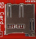
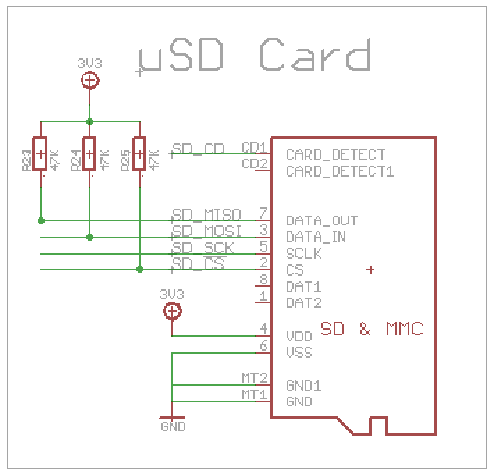
A microSD socket that provides several Gigabytes worth of file system space for classic computing systems.
| Name | Direction | Function | Arduino Pin | Papilio Wing Pin | ATmega32U4 Pin | Spartan 6 FPGA Pin |
| SD CD | Input | Card Detect | D3 | AL3 | B4 | P119 |
| SD MISO | Input | Master In Slave Out | D2 | AL2 | B5 | P118 |
| SD MOSI | Output | Master Out Slave In | D14 | BL7 | B6 | P115 |
| SD SCK | Input | D15 | BL6 | C6 | P114 | |
| SD CS | Input | Chip Select | D16 | BL7 | C7 | P112 |
Classic Computing Shield VGA
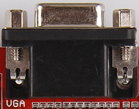
The VGA section of the Computing Shield uses 12 resistors to implement 4K color depth. VGA video is analog in nature so there needs to be some way to vary the RGB (Red, Green, and Blue) signals between 0V and .7V. For each RGB signal the shade, or intensity, of the color is controlled by varying the voltage of the pin between 0 and .7V. The finer control you have over the voltage the more colors you can create. For the Computing Shield we are able to control 4 different bits per color which allows us to generate 16 different voltage levels between 0 and .7V. This means we can generate 16 shades for each color. If we add all three colors together we have 12 bit video which gives us (2^12=4096) the possibility of 4096 colors.
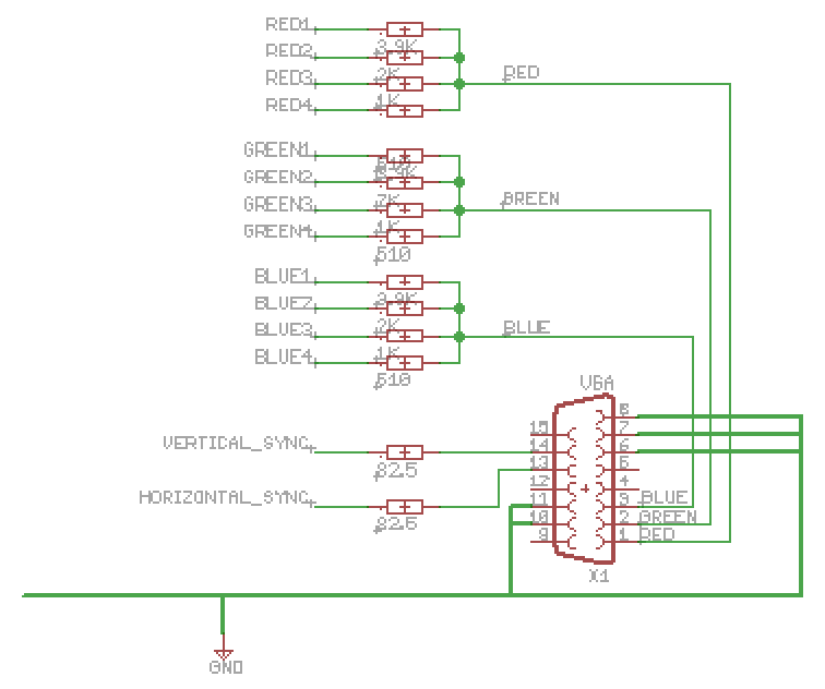
The usual options for controlling voltage on a pin are to use a DAC, PWM, Delta-Sigma, or a resistor ladder. For the Arcade Wing we wanted to use the lowest cost and easiest method for a hobbyist. PWM and Delta-Sigma were ruled out because we did not think we would be able to vary the voltage with these methods fast enough to keep up with the VGA timing requirements. A DAC would be a good solution but was more than we needed for our modest requirements. A resistor ladder fit the bill perfectly because it is very low cost and easy to implement. The resistor ladder is made up of 4 resistors per RGB color that all connect, in common, to the VGA connector on one side and individually to a digital I/O pin on the other side. The lowest resistor starts at ~500 ohms and each successive resistor doubles in size with the final resistor ending with ~4K ohms. Each digital I/O pin is controlled by the VGA controller inside the FPGA. Each pin can be set to either 0 or 1 with a 1 causing the resistor to contribute its voltage to the final voltage level. The voltage can be stepped up from 0 to the desired output voltage which in this case is .7V.
| Name | Direction | Function | Arduino Pin | Papilio Wing Pin | ATmega32U4 Pin | Spartan 6 FPGA Pin |
| Red1 | Output | Red Bit 1 | D52 | CH7 | P47 | |
| Red2 | Output | Red Bit 2 | D50 | CH6 | P50 | |
| Red3 | Output | Red Bit 3 | D48 | CH5 | P55 | |
| Red4 | Output | Red Bit 4 | D46 | CH4 | P57 | |
| Green1 | Output | Green Bit 1 | D38 | CH0 | P75 | |
| Green2 | Output | Green Bit 2 | D40 | CH1 | P67 | |
| Green3 | Output | Green Bit 3 | D42 | CH2 | P62 | |
| Green4 | Output | Green Bit 4 | D44 | CH3 | P59 | |
| Blue1 | Output | Blue Bit 1 | D26 | CL2 | P93 | |
| Blue2 | Output | Blue Bit 2 | D32 | CL5 | P83 | |
| Blue3 | Output | Blue Bit 3 | D34 | CL6 | P81 | |
| Blue4 | Output | Blue Bit 4 | D36 | CL7 | P79 | |
| VSync | Output | Vertical Sync | D24 | CL1 | P97 | |
| HSync | Output | Horizontal Sync | D22 | CL0 | P99 |
The way the desired output voltage is accomplished is by carefully managing the parallel voltage that the 4 resistors add up to. Using a Parallel Resistance Calculator we see that 500 ohm, 1000 ohm, 2000 ohm, and 4000 ohm give a total resistance of 266 ohm. The final key bit of information is that there is a 75 ohm resistance built into VGA cables, so that means that the point where our 4 resistors come together on our VGA connector forms a Voltage divider circuit. Using a Voltage Divider calculator with 3.3V as the Input Voltage, 266 ohm as R1, and 75 ohm as R2 we end up with an Output Voltage of .73V. The end result is that if all 4 resistors are set to �1� then we will see .73V at the VGA connector. If all 4 resistors are set to �0� then we will see 0V at the VGA connector, any combinations in between will give us evenly stepped voltages between 0 and .73V. The voltages will be evenly stepped because we picked resistors that double in size.
Classic Computing Shield Sound
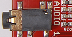

The sound section implements a 1/8th inch mono jack with a low pass filter. Projects simply implement a Delta-Sigma DAC as outlined in Xilinx App Note 154. A Delta-Sigma DAC allows high quality audio to be implemented with a minimum amount of physical hardware required. The high speed of the FPGA clock allows the FPGA to do the heavy lifting of the Digital to Analog conversion.
| Name | Direction | Function | Arduino Pin | Papilio Wing Pin | ATmega32U4 Pin | Spartan 6 FPGA Pin |
| Audio1-Left | Output | Audio Output1 Left | D28 | CL3 | P88 | |
| Audio1-Right | Output | Audio Output1 Right | D30 | CL4 | P85 | |
| Audio2-Left | Output | Audio Output2 Left | D45 | DL4 | P58 | |
| Audio2-Right | Output | Audio Output2 Right | D43 | DL5 | P61 |
Classic Computing Shield Joystick
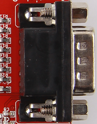
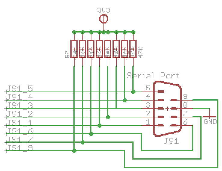
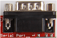
The Computing Shield supports Atari 2600, Commodore 64, classic Arcade joystick, and any joystick that uses digital inputs. The board comes with a Male DB9 connector that allows an Atari 2600 joystick to be plugged in and used without any custom wiring. For a custom Arcade style joystick it is necessary to wire the joystick to a female DB9 connector using the diagram below.
Joystick A
| Name | Direction | Function | Arduino Pin | Papilio Wing Pin | ATmega32U4 Pin | Spartan 6 FPGA Pin |
| JS1 1 | Input | Up | D13 | B1 | P134 | |
| JS1 2 | Input | Down | D11 | B2 | P132 | |
| JS1 3 | Input | Left | D9 | B7 | P127 | |
| JS1 4 | Input | Right | D8 | D0 | P126 | |
| JS1 5 | Input | Fire 2 | D6 | AL6 | D4 | P123 |
| JS1 6 | Input | Fire 1 | D12 | B3 | P133 | |
| JS1 7 | Input | 5v | D10 | B0 | P131 | |
| JS1 9 | Input | Select | D7 | AL7 | B2 | P124 |
Joystick B
| Name | Direction | Function | Arduino Pin | Papilio Wing Pin | ATmega32U4 Pin | Spartan 6 FPGA Pin |
| JS2 1 | Input | Up | D31 | DH3 | P84 | |
| JS2 2 | Input | Down | D29 | DH4 | P87 | |
| JS2 3 | Input | Left | D27 | DH5 | P92 | |
| JS2 4 | Input | Right | D25 | DH6 | P95 | |
| JS2 5 | Input | Fire 2 | D23 | DH7 | P98 | |
| JS2 6 | Input | Fire 1 | D33 | DH2 | P82 | |
| JS2 7 | Input | 5v | D35 | DH1 | P80 | |
| JS2 9 | Input | Select | D37 | DH0 | P78 |
Classic Computing Shield RS232 UART
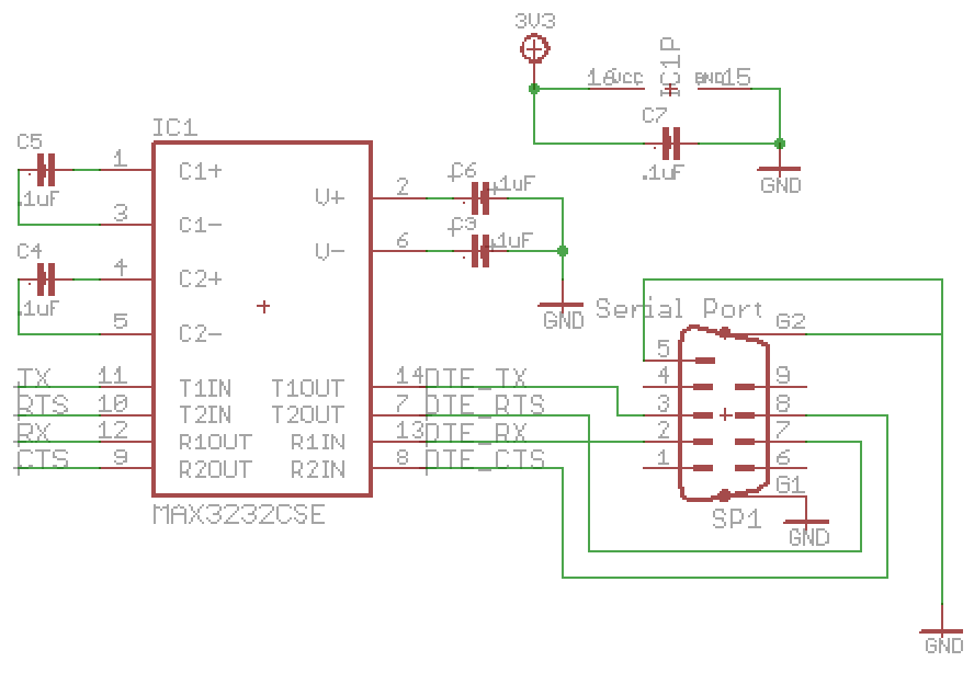
The RS232 serial port allows peripherals that need RS232 voltage levels to be connected to the Computing Shield.
| Name | Direction | Function | Arduino Pin | Papilio Wing Pin | ATmega32U4 Pin | Spartan 6 FPGA Pin |
| RX | Input | RS232 Receive | D0 | AL0 | D2 | P116 |
| TX | Output | RS232 Send | D1 | AL1 | D3 | P117 |
Computing Shield Directional Buttons
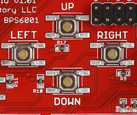

The Computing Shield has 4 momentary switches arranged in a plus configuration that can be used for user input or video games!
| Name | Direction | Function | Arduino Pin | Papilio Wing Pin | ATmega32U4 Pin | Spartan 6 FPGA Pin |
| Up | Input | Directional Button Up | D20 | P101 | ||
| Down | Input | Directional Button Down | D18 | P105 | ||
| Left | Input | Directional Button Left | D17 | P111 | ||
| Right | Input | Directional Button Right | D21 | P100 |
Computing Shield LED�s
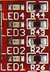
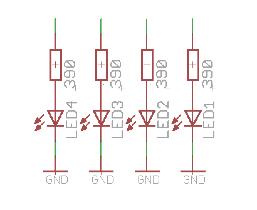
The Computing Shield provides 4 LED�s.
| Name | Direction | Function | Arduino Pin | Papilio Wing Pin | ATmega32U4 Pin | Spartan 6 FPGA Pin |
| Led1 | Output | Led 1 | D47 | DL3 | P56 | |
| Led2 | Output | Led 2 | D49 | DL2 | P51 | |
| Led3 | Output | Led 3 | D51 | DL1 | P48 | |
| Led4 | Output | Led 4 | D53 | DL0 | P39 |
Computing Shield Keyboard and Mouse
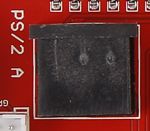
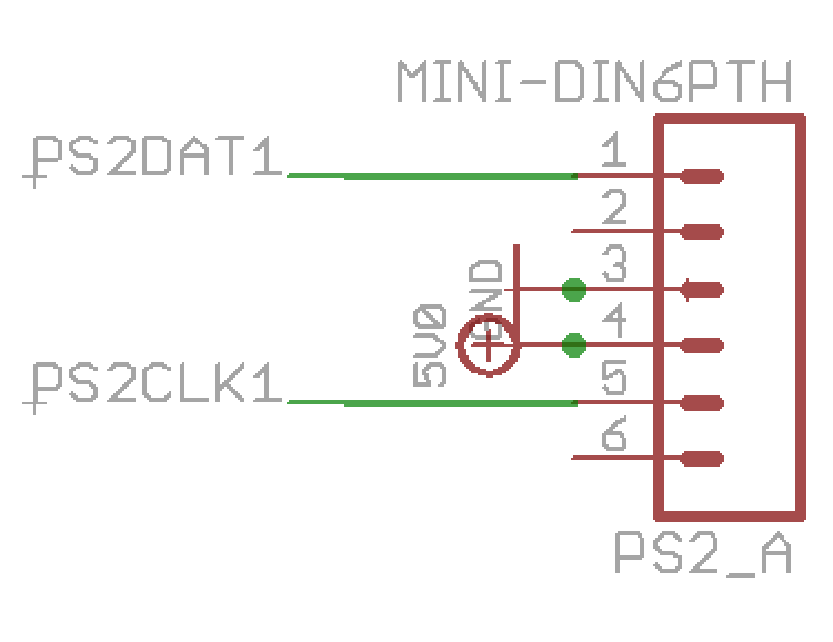
The Computing Shield has two PS/2 ports that can be used to connect a keyboard and mouse.
| Name | Direction | Function | Arduino Pin | Papilio Wing Pin | ATmega32U4 Pin | Spartan 6 FPGA Pin |
| PS/2 A CLK | Output | Clock | D5 | AL5 | D6 | P121 |
| PS/2 A Data | Input | Data | D4 | AL4 | D7 | P120 |
| PS/2 B CLK | Output | Clock | D39 | DL7 | P74 | |
| PS/2 B Data | Input | Data | D41 | DL6 | P66 |
Images
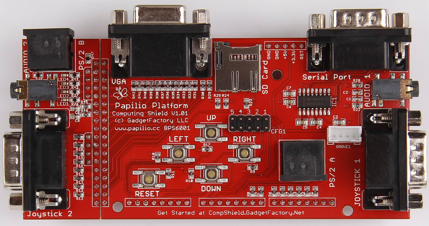
Classic Computing Shield High Resolution Image
Click the image to load a High Resolution image of the Classic Computing Shield
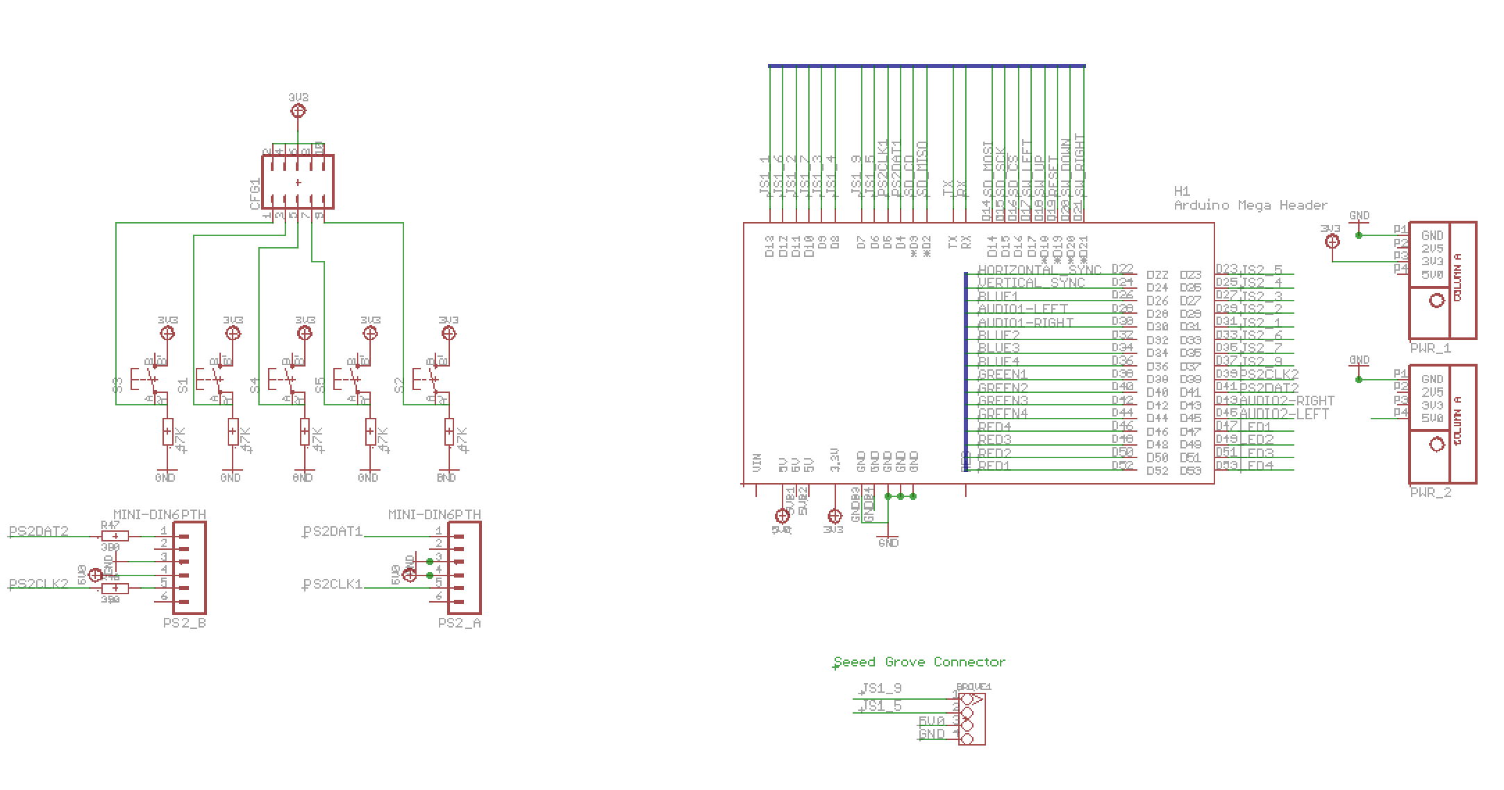
Classic Computing Shield Schematic
Click the image to load a PDF version of the Classic Computing Shield Schematic
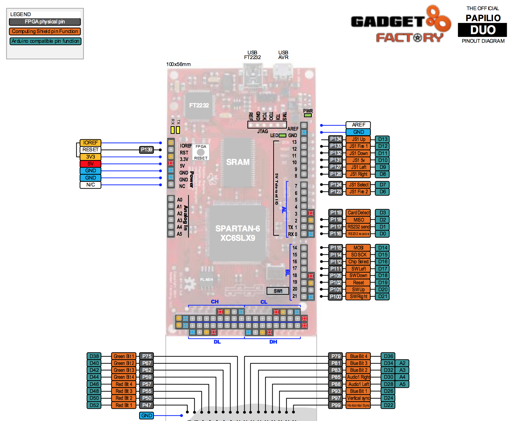
Papilio DUO Pinouts
Click the image to load a PDF version of Papilio DUO pinouts diagram