
(:notabledit:)
Hardware | Papilio DUO - Papilio One - Papilio Pro - MegaWings - Wings - Shields
Contents
Overview
Specifications
Demo Video
LogicStart 7 Segment Display
LogicStart VGA
LogicStart Sound
LogicStart Micro-Joystick
LogicStart SPI ADC
LogicStart LED�s and Switches
Images
LogicStart MegaWing
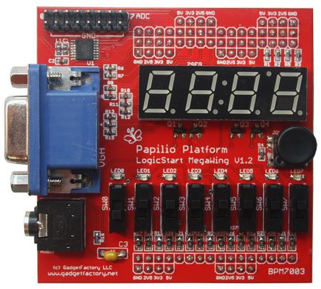
The LogicStart MegaWing provides everything needed to get started with VHDL and FPGA development on the Papilio with one convenient and easy to connect circuit board.
Learn VHDL with Mike Field's free book written specifically for the Papilio and LogicStart MegaWing. Step by step examples and full source code walks you through using all the peripherals on the LogicStart.
Dive into the exciting world of customizable Soft Processor's with the ZPUino. Custom peripheral's such as a ZX Spectrum compatible VGA adapter and classic audio chips are just a few of the exciting possibilities. The LogicStart gives you peripherals to experiment with!
Explore the VHDL source code of classic video games such as Pac-Man! The LogicStart's VGA output and Micro-Joystick allow all of the Papilio Arcade games to be synthesized.
Discover all the projects that work with the LogicStart MegaWing or contribute your own!
Specifications
- 7 Segment Display - 4 Character
- VGA Port - 3r,3g,2b VGA Output
- Mono Audio Jack - 1/8" Jack, Low Pass Filter
- Micro-Joystick - 5 directions
- SPI ADC - 12-bit, 1Msps, 8 Channel
- 8 LED's - User Feedback
- 8 Slide Switches - User Input
Quicklinks
- Buy the LogicStart MegaWing Now!
- Download a PDF version of Mike Fields book
- Source code for Mike Fields book
- LogicStart MegaWing Generic UCF
- LogicStart MegaWing Project Showcase
- Collection of open-source books on VHDL
- ADC128S102 SPI ADC Datasheet
Demo Video
Peripherals
LogicStart 7 Segment Display
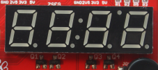
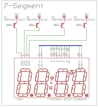
The 7 Segment Display provides 4 character displays with a dot between each character. It is great for displaying anything from high speed debugging data to a low speed alarm clock.
| Name | Direction | Function | Arduino Pin | Papilio Wing Pin | Papilio One Pin | Papilio Pro Pin |
| A | Output | A Segment | 7 | A7, AL7 | P57 | P75 |
| B | Output | B Segment | 10 | A10, AH2 | P65 | P83 |
| C | Output | C Segment | 5 | A5, AL5 | P40 | P66 |
| D | Output | D Segment | 6 | A6, AL6 | P53 | P67 |
| E | Output | E Segment | 3 | A3, AL3 | P33 | P58 |
| F | Output | F Segment | 4 | A4, AL4 | P35 | P61 |
| G | Output | G Segment | 9 | A9, AH1 | P62 | P81 |
| DP | Output | Data Point Segment | 1 | A1, AL1 | P23 | P51 |
| AN0 | Output | AN0 | 11 | A11, AH3 | P67 | P85 |
| AN1 | Output | AN1 | 8 | A8, AH0 | P60 | P79 |
| AN2 | Output | AN2 | 2 | A2, AL2 | P26 | P56 |
| AN3 | Output | AN3 | 0 | A0, AL0 | P18 | P48 |
LogicStart VGA
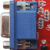
The VGA section of the LogicStart MegaWing uses 8 resistors to implement 256 color depth. VGA video is analog in nature so there needs to be some way to vary the RGB (Red, Green, and Blue) signals between 0V and .7V. For each RGB signal the shade, or intensity, of the color is controlled by varying the voltage of the pin between 0 and .7V. The finer control you have over the voltage the more colors you can create. For the LogicStart MegaWing we are able to control 3 Red, 3 Green, and 2 Blue bits which allows us to generate 8 different voltage levels between 0 and .7V for Red and Green and 4 voltage levels for Blue. If we add all three colors together we have 8 bit video which gives us (2^8=256) the possibility of 256 colors.

The usual options for controlling voltage on a pin are to use a DAC, PWM, Delta-Sigma, or a resistor ladder. For the LogicStart MegaWing we wanted to use the lowest cost and easiest method for a hobbyist. PWM and Delta-Sigma were ruled out because we did not think we would be able to vary the voltage with these methods fast enough to keep up with the VGA timing requirements. A DAC would be a good solution but was more than we needed for our modest requirements. A resistor ladder fit the bill perfectly because it is very low cost and easy to implement. The resistor ladder is made up of 3r, 3g, 2b resistors that all connect, in common, to the VGA connector on one side and individually to a digital I/O pin on the other side. Each digital I/O pin is controlled by the VGA controller inside the FPGA. Each pin can be set to either 0 or 1 with a 1 causing the resistor to contribute its voltage to the final voltage level. The voltage can be stepped up from 0 to the desired output voltage which in this case is .7V.
| Name | Direction | Function | Arduino Pin | Papilio Wing Pin | Papilio One Pin | Papilio Pro Pin |
| Red0 | Output | Red Bit 0 | 23 | B7, BL7 | P61 | P78 |
| Red1 | Output | Red Bit 1 | 24 | B8, BH0 | P58 | P74 |
| Red2 | Output | Red Bit 2 | 25 | B9, BH1 | P54 | P95 |
| Green0 | Output | Green Bit 0 | 20 | B4, BL4 | P68 | P84 |
| Green1 | Output | Green Bit 1 | 21 | B5, BL5 | P66 | P82 |
| Green2 | Output | Green Bit 2 | 22 | B6, BL6 | P63 | P80 |
| Blue0 | Output | Blue Bit 0 | 18 | B2, BL2 | P78 | P92 |
| Blue1 | Output | Blue Bit 1 | 19 | B3, BL3 | P71 | P87 |
| VSync | Output | Vertical Sync | 16 | B0, BL0 | P85 | P99 |
| HSync | Output | Horizontal Sync | 17 | B1, BL1 | P83 | P97 |
LogicStart Sound
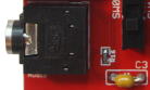

The sound section implements a 1/8th inch mono jack with a low pass filter. Projects simply implement a Delta-Sigma DAC as outlined in Xilinx App Note 154. A Delta-Sigma DAC allows high quality audio to be implemented with a minimum amount of physical hardware required. The high speed of the FPGA clock allows the FPGA to do the heavy lifting of the Digital to Analog conversion.
| Name | Direction | Function | Arduino Pin | Papilio Wing Pin | Papilio One Pin | Papilio Pro Pin |
| Audio | Output | Audio Output | 26 | B10, BH2 | P41 | P62 |
LogicStart Micro-Joystick


The LogicStart MegaWing has a 5 direction micro-joystick that can be used for user input or video games!
| Name | Direction | Function | Arduino Pin | Papilio Wing Pin | Papilio One Pin | Papilio Pro Pin |
| Select | Input | Press Joystick In | 31 | B15, BH7 | P22 | P47 |
| Up | Input | Press Joystick Up | 30 | B14, BH6 | P25 | P50 |
| Down | Input | Press Joystick Down | 29 | B13, BH5 | P32 | P55 |
| Left | Input | Press Joystick Left | 28 | B12, BH4 | P34 | P57 |
| Right | Input | Press Joystick Right | 27 | B11, BH3 | P36 | P59 |
LogicStart SPI ADC
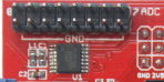
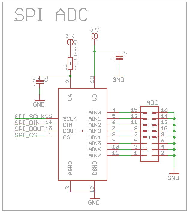
The SPI ADC allows pots, pot slides, temp sensors, and many more analog devices to be connected, up to 8 devices at once.
The SPI ADC uses the ADC128S102 chip from National.
| Name | Direction | Function | Arduino Pin | Papilio Wing Pin | Papilio One Pin | Papilio Pro Pin |
| CLK | Output | Clock | 15 | A15, AH7 | P86 | P100 |
| MOSI | Output | Master Out Slave In | 14 | A14, AH6 | P84 | P98 |
| MISO | Input | Master In Slave Out | 13 | A13, AH5 | P79 | P93 |
| CS | Output | Chip Select (Active Low) | 12 | A12, AH4 | P70 | P88 |
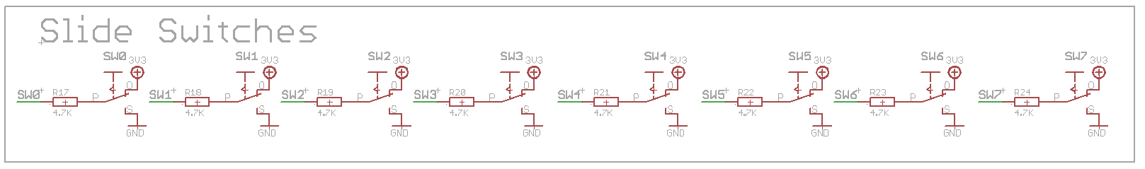
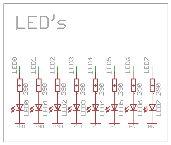
LogicStart LED�s and Switches
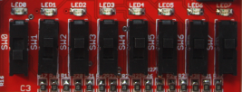
The LogicStart MegaWing provides 8 LED�s and 8 Slide Switches.
| Name | Direction | Function | Arduino Pin | Papilio Wing Pin | Papilio One Pin | Papilio Pro Pin |
| Led0 | Output | Led 0 | 40 | C8, CH0 | P5 | P123 |
| Led1 | Output | Led 1 | 41 | C9, CH1 | P9 | P124 |
| Led2 | Output | Led 2 | 42 | C10, CH2 | P10 | P126 |
| Led3 | Output | Led 3 | 43 | C11, CH3 | P11 | P127 |
| Led4 | Output | Led 4 | 44 | C12, CH4 | P12 | P131 |
| Led5 | Output | Led 5 | 45 | C13, CH5 | P15 | P132 |
| Led6 | Output | Led 6 | 46 | C14, CH6 | P16 | P133 |
| Led7 | Output | Led 7 | 47 | C15, CH7 | P17 | P134 |
| SW0 | Input | Switch 0 | 32 | C0, CL0 | P91 | P114 |
| SW1 | Input | Switch 1 | 33 | C1, CL1 | P92 | P115 |
| SW2 | Input | Switch 2 | 34 | C2, CL2 | P94 | P116 |
| SW3 | Input | Switch 3 | 35 | C3, CL3 | P95 | P117 |
| SW4 | Input | Switch 4 | 36 | C4, CL4 | P98 | P118 |
| SW5 | Input | Switch 5 | 37 | C5, CL5 | P2 | P119 |
| SW6 | Input | Switch 6 | 38 | C6, CL6 | P3 | P120 |
| SW7 | Input | Switch 7 | 39 | C7, CL7 | P4 | P121 |
Images

LogicStart MegaWing High Resolution Image
Click the image to load a High Resolution image of the LogicStart MegaWing
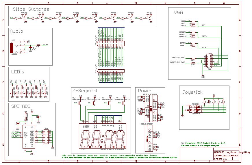
LogicStart MegaWing Schematic
Click the image to load a PDF version of the LogicStart MegaWing Schematic

Assembly View
Click the image for a full size view of the boards part layout.