
(:notabledit:)
Hardware | Papilio DUO - Papilio One - Papilio Pro - MegaWings - Wings - Shields
Contents
Overview
Spartan 6 LX9 FPGA
AVR ATmega32U4
Power
Dual Channel USB
SRAM
SPI Flash
I/O
Oscillator
User Switch
JTAG
Reset
User LED
Links
License
Images
Papilio DUO Hardware Guide
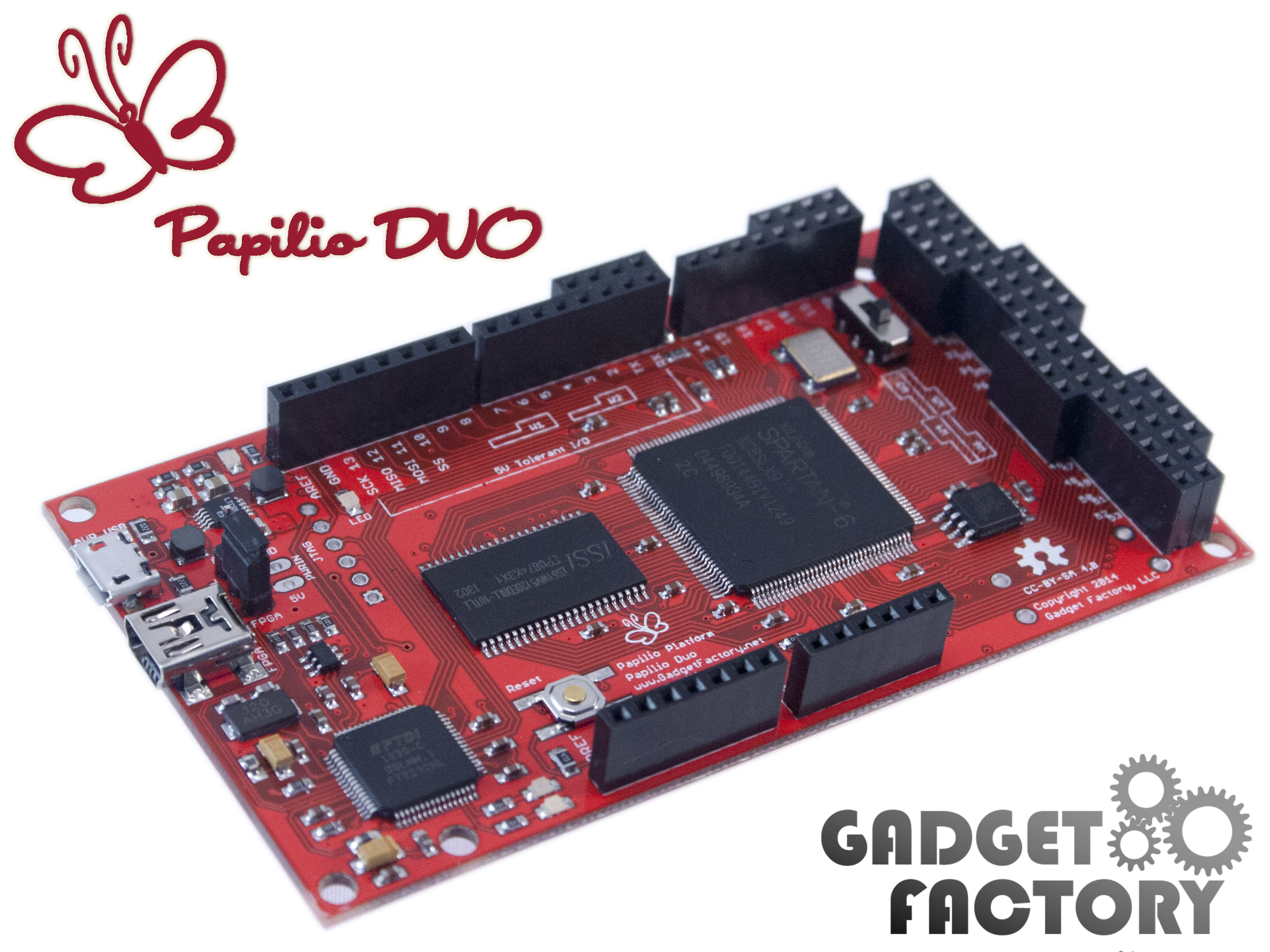
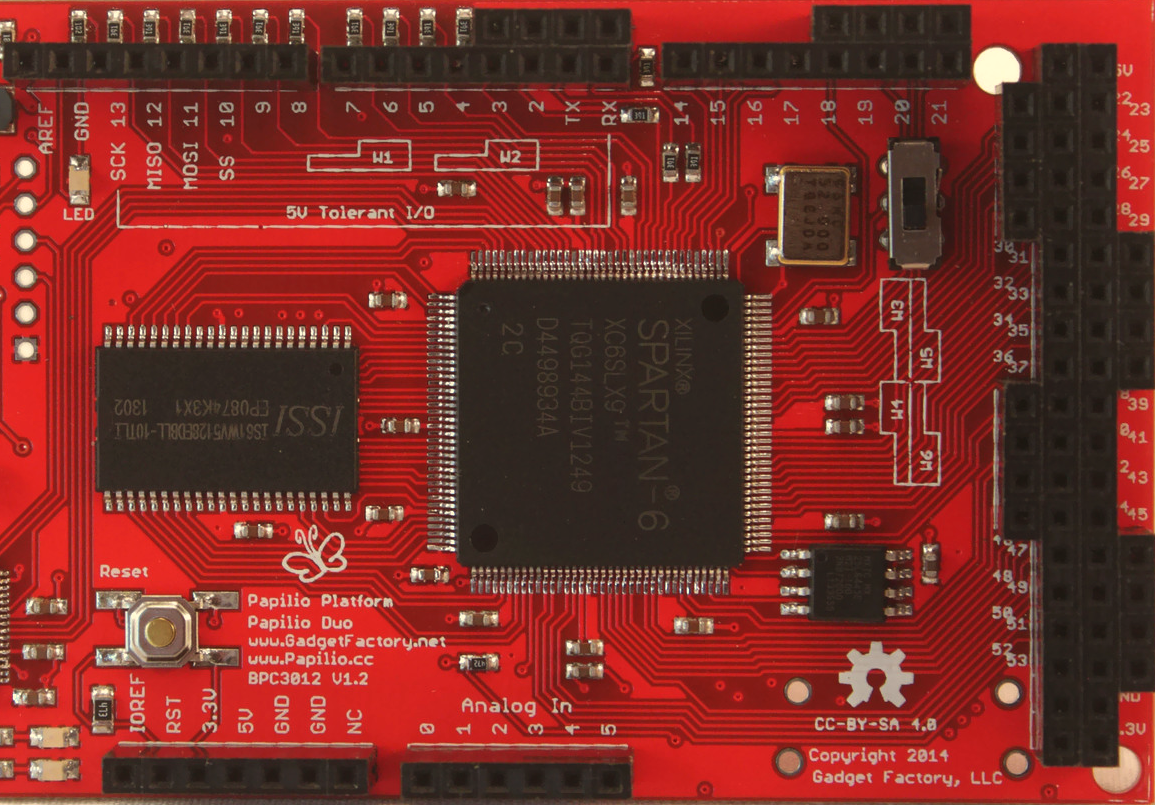
The Papilio DUO is an Open Source FPGA development board designed with the Arduino Mega footprint. It has a Spartan 6 FPGA on the top and an AVR Atmega32U4 (the same chip used in the Arduino Leonardo) on the bottom. It has 54 I/O lines, dual channel USB, integrated JTAG programmer, 512KB or 2MB of SRAM, and an efficient switching power supply.
- Spartan 6 LX9 FPGA (Datasheet)
- AVR ATmega32U4 Microcontroller (Datasheet)
- High efficiency LTC3419 Step Down Dual Voltage Regulator (Datasheet)
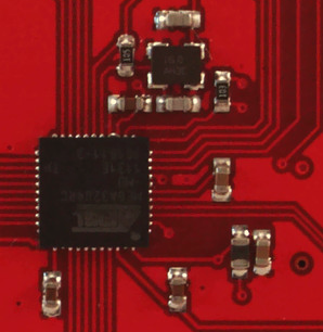
- Dual Channel FTDI FT2232H USB 2.0 High Speed Interface (Datasheet)
- 512KB ISSI IS61WV5128BLL SRAM (Datasheet) OR 2MB ISSI IS61WV20488BLL SRAM (Datasheet)
- 64Mbit Macronix MX25L6445 SPI Flash (Datasheet)
- 54 I/O pins arranged in a Arduino Mega form factor
- 32Mhz Crystal Oscillator
Spartan 6 LX9 FPGA
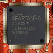
The Papilio DUO's Spartan 6 FPGA offers some exciting features:
Digital Signal Processing (DSP) Slices
Clock Management Tile (CMT)
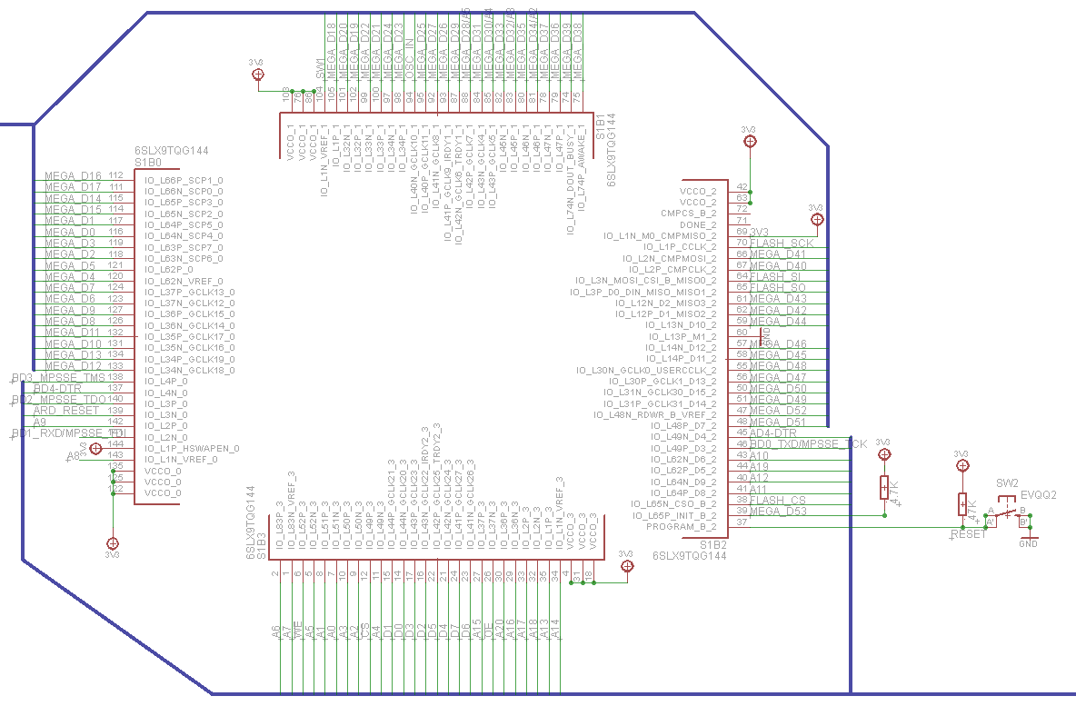
FPGA Schematic
New I/O Standards
Multi-Boot Support
BRAM Memory Blocks
| Papilio Board | 18Kbit BRAM Blocks | Max SRAM | Usable SRAM |
| Papilio DUO | 32 | 576Kbit (72KByte) | 512Kbit (64KByte) |
| Papilio One 500K | 20 | 360Kbit (45KByte) | 320Kbit (40KByte) |
| Papilio One 250K | 12 | 216Kbit (27KByte) | 192Kbit (24KByte) |
BRAM's are 18Kbit in size including two parity bits. In most cases the two parity bits are not used so the BRAM's usable size becomes 16Kbit. If your design can use an 18 bit wide bus then it is possible to utilize the parity bits for data and gain access to all 18Kbit memory space.
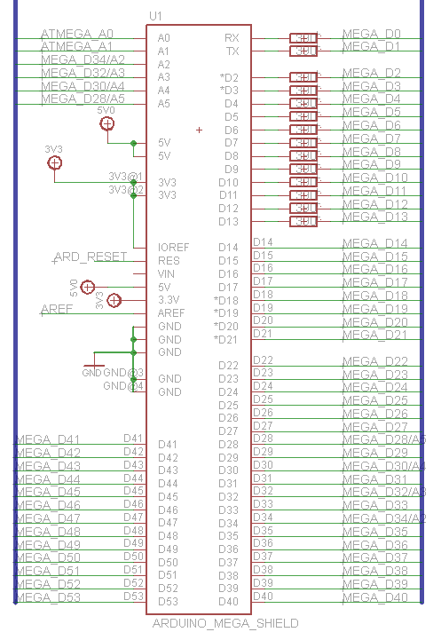
ATmega32U4 "Arduino Leonardo" compatible Microcontroller
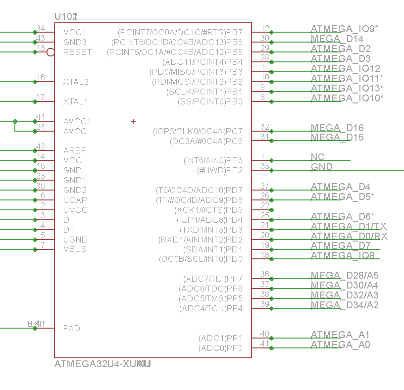
The ATmega32U4 chip is a unique addition that gives full Arduino compatibility to the Papilio DUO. It is derived from the Arduino Leonardo design.
Arduino Leonardo Compatibility
While the ATmega32U4 design is derived from the Arduino Leonardo design it was necessary to re-order the location of the pins to achieve routing of the design on a single layer. This means that the ISP, PWM, and I2C pins are not in the same location as they are on the Leonardo. In the case of the SPI pins they are located in the same location as the Arduino UNO which is actually more convenient. The different pin locations is handled by a pin mapping in the DesignLab IDE which makes everything work just the same as the Arduino Leonardo does. As long as you use the DesignLab IDE and select the Papilio DUO - AVR board type the pin locations will be mapped correctly. Using the Arduino Leonardo board type will not give the expected results since the pins will be in the wrong locations. It is possible to take the Papilio DUO variant from the DesignLab IDE and add it to the Arduino IDE, we will try to provide a package for this in the future.
Power
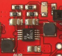
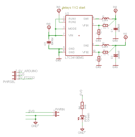
Power Schematic
One of the strengths of the Papilio DUO is its power supply. The Spartan 6 simplifies the power requirements which allowed us to use a high efficiency LTC3419 switching power supply at about the same component cost as the Papilio One's power supply. The linear regulators used in the Papilio One would noticeably heat up when a complicated, high speed design, like the ZPUino, was running. With the Papilio DUO there is no detectable heat generated, even when the most demanding designs are running!
Dual Channel USB
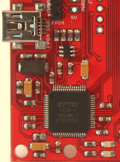
The Papilio DUO uses the upgraded FT2232H dual channel USB chip. The FT2232H is an upgrade from the FT2232D used in previous Papilio boards. It has MPSSE on both channels and can achieve higher speeds.
- Channel A is connected to the JTAG pins of the Papilio DUO and provides very fast programming of the FPGA (500mS).
- Channel B is connected to the Papilio DUO in an Asynchronous serial UART configuration that is capable of speeds up to 3MHz.
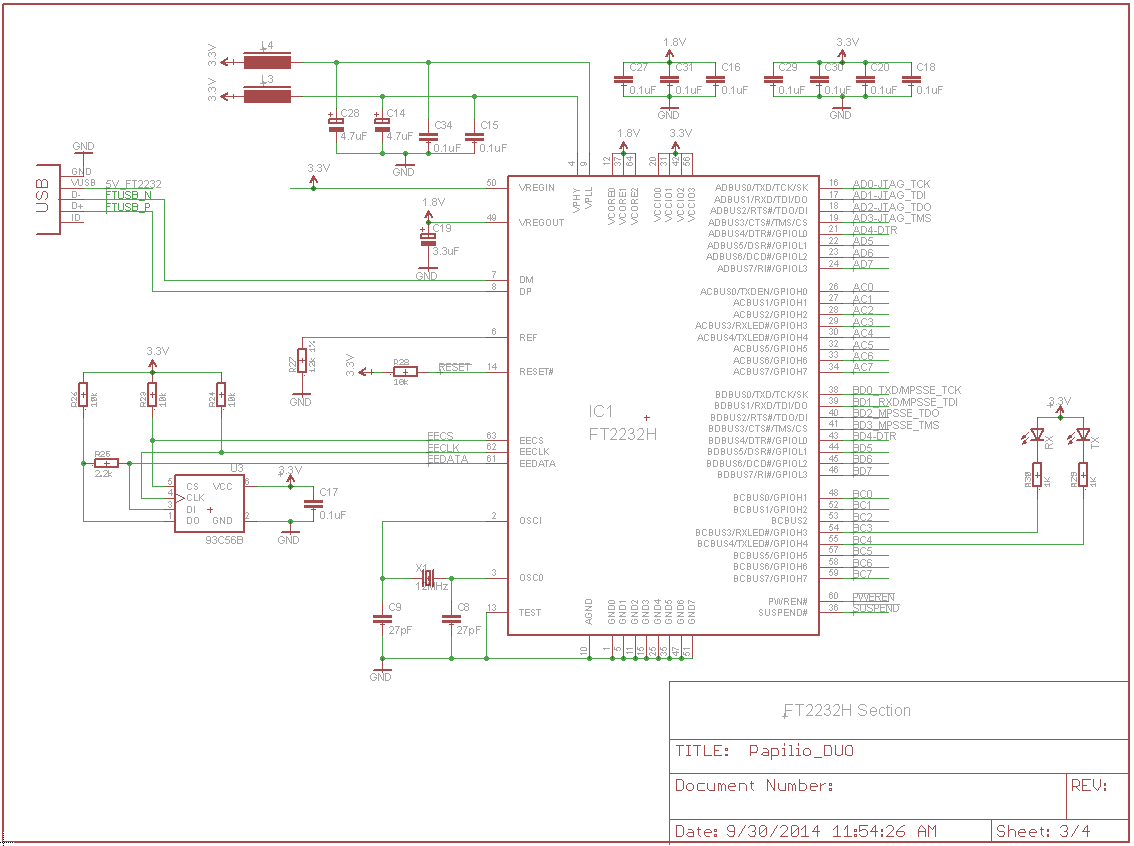
USB Schematic
| Name | Direction (FPGA Perspective) | Function | Arduino Pin | Papilio Wing Pin | Papilio DUO Pin |
| RX | Input | FPGA Serial Receive (MISO) | N/A | N/A | P46 |
| TX | Output | FPGA Serial Transmit (MOSI) | N/A | N/A | P141 |
SRAM
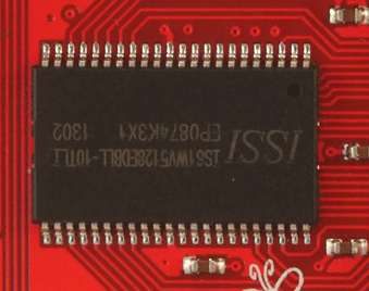
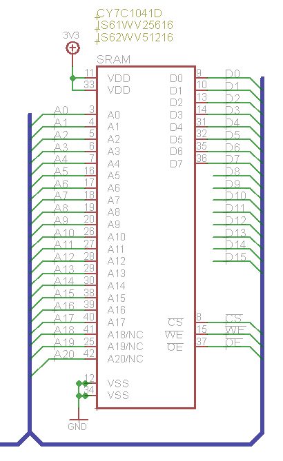
The Papilio DUO includes a 512KB ISSI IS61WV5128BLL or 2MB ISSI IS61WV20488BLL SRAM chip. SRAM is much, much easier to use with FPGA projects since there are no special timing requirements to follow. While we don't get as much SRAM memory space as we would for the same priced SDRAM or DDR memory chip, the trade off in ease of use more then makes up for it.
The ZPUino Soft Processor integrates the SRAM which gives your ZPUino sketches 512KB or 2MByte of code space!
SPI Flash

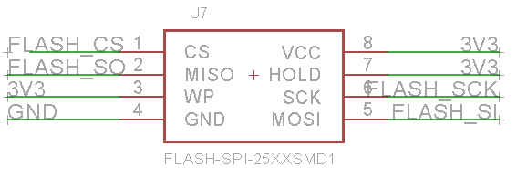
The 64Mbit Macronix MX25L6445 SPI Flash chip is the largest ever included with a Papilio FPGA. It is the largest available in the 8-SOIC footprint, and is included for good reason! The new multi-boot feature of the Spartan 6 means we can put as many FPGA bit files on the SPI Flash as will fit and use a "golden image" to select which one will boot at startup. Spartan 6 LX9 bit files are 333KBytes in size which means that the Papilio DUO can save up to 23 bit files in SPI Flash. Or, we can save and retrieve user data using techniques like the SmallFS filesystem or bootstrap code that loads data from SPI Flash to SRAM at startup.
| Name | Direction (FPGA Perspective) | Function | Arduino Pin | Papilio Wing Pin | Papilio DUO Pin |
| FLASH_CS | Output | SPI Flash Chip Select | N/A | N/A | P38 |
| FLASH_CLK | Output | SPI Flash Clock | N/A | N/A | P70 |
| FLASH_MOSI | Output | SPI Flash Master Out Slave In (MOSI) | N/A | N/A | P64 |
| FLASH_MISO | Input | SPI Flash Master In Slave Out (MISO) | N/A | N/A | P65 |
I/O
The Papilio DUO is unique in that it is the first Papilio board to adopt the Arduino Mega form factor. The Arduino form factor gives us 54 I/O pins and 6 Analog pins.
Shared Pins - Digital IO Pins 0-16 are connected to both the ATmega32U4 and the Spartan 6 FPGA. These pins can be used to transfer data between the two chips, provide digital logic to the AVR chip, connect a Logic Analyzer to the AVR chip, or transfer Analog data to the FPGA; to name a few uses. The AVR is set to run at 3.3V so there is no voltage mismatch between the AVR and FPGA. 5V tolerance for shields is implemented as described below.
Shared Pins - Analog Analog pins 2-5 on the ATmega32U4 are shared with the FPGA because they are dual purpose pins, both analog and JTAG. A2-5 are connected to Pins 28, 30, 32, and 34 which allows the FPGA to act as a debugger for the ATmega32U4.
Analog Pins There are six analog pins on the Papilio DUO. Since an FPGA does not natively support Analog input we are using the ATmega32U4 to implement the analog pins. The Analog pins must be read from the ATmega32U4, if their output is needed on the FPGA then we recommend using the AVR to Wishbone bridge to transfer their value. Or alternatively, read their value with the ATmega32U4 and place the result on the shared pins 0-7 to be read by the FPGA.
FPGA Only Pins Pins 17-53 are connected exclusively to the FPGA and are 3.3V without 5V tolerance. The exception is pins 28, 30, 32, and 34 which are also connected to the JTAG pins of the ATmega32U4 in order to allow step by step debugging.
ATmega32U4 JTAG Pins The ATmega32U4 JTAG pin fuses are enabled by default so that JTAG debugging is enabled at power on. In order to prevent the JTAG pins, which are shared with FPGA pins, from interfering with normal operation the JTAG registers are set to disable the JTAG pins when a sketch is loaded.
5V Tolerance The first 14 pins, those that comprise the shortened Arduino Uno footprint, are 5V tolerant. This means that you can safely attach any of your 5V Arduino shields without damaging the 3.3V pins of the FPGA.
5V tolerance is accomplished by placing series current limiting resistors in line with the FPGA pins. This is a common and widely accepted practice with Xilinx FPGA's and has been tested extensively. These resistors protect from too much current being applied to the FPGA pins and the internal clamp diodes on the pins convert the extra voltage into reverse current. So as long as our power supply can safely handle reverse current, which it can, we achieve 5V tolerance. For those interested in learning more there is an interesting discussion here.
Please note that 5V tolerance means that you can connect 5V logic to these pins but the pins are not driven at 5V. The pins provide 3.3V which is high enough to trigger a "High" state for 5V logic levels. A few boards, such as RAMPS, need a full 5 Volts to work correctly. Unfortunately 5V tolerance will not work with these rare cases.
Oscillator

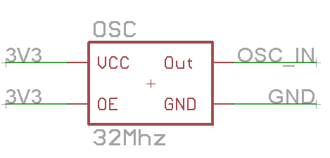
The Papilio DUO has a 32Mhz oscillator that can be converted to any speed desired inside the FPGA using the Clock Management Tile (CMT). There are two PLLs and two Digital Clock Managers (DCM) available for your designs.
| Name | Direction (FPGA Perspective) | Function | Arduino Pin | Papilio Wing Pin | Papilio DUO Pin |
| CLK | Input | External 32Mhz Oscillator | N/A | N/A | P94 |
User Switch
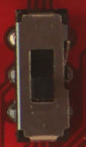
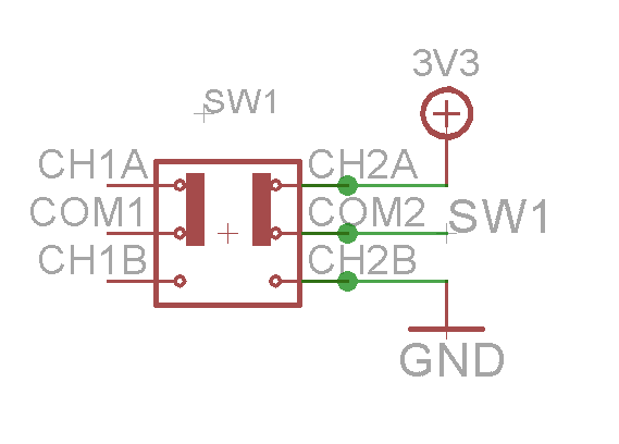
The Papilio DUO has a user switch (SW1) that can be used for any purpose required. By default most Papilio DUO circuits have the switch setup to enable or disable the AVR.
If your circuit implements the default AVR reset then putting SW1 to the up position turns the AVR on, while putting it in the down position turns it off. Please be do not be confused if the switch does not work this way. It only works if the circuit you have loaded sets up the switch to work this way. For example, the circuit that is loaded to the Papilio DUO from the factory is not setup to work this way. Instead it hard wires the AVR to always be on.
JTAG

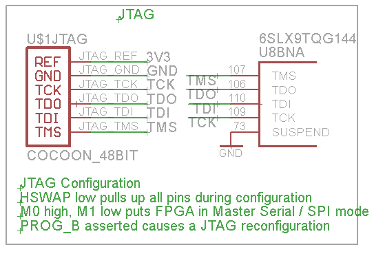
The JTAG header on the Papilio DUO is provided for use with external programmers:
Use a Xilinx Programming Cable
An external programmer may not be necessary to use the Xilinx tools. The Papilio DUO may be detected by the Digilent cable plugin which will allow it to be used with the Xilinx tools. This is an unsupported feature that may or may not work. We recommend using the Papilio tools to load bit files to the Papilio, but if you need to use the Papilio with the EDK or Chipscope software then check to see if the Digilent plugin detects your board. If not then we recommend using the JTAG port with an external programmer.
| Name | Direction (FPGA Perspective) | Function | Arduino Pin | Papilio Wing Pin | Papilio DUO Pin |
| JTAG_TMS | Input | JTAG TMS | N/A | N/A | P107 |
| JTAG_TCK | Input | JTAG TCK | N/A | N/A | P109 |
| JTAG_SI | Input | JTAG SI | N/A | N/A | P64 |
| JTAG_SO | Output | JTAG SO | N/A | N/A | P65 |
FPGA Reset
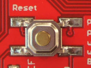
Pressing the reset button will cause the Spartan 6 FPGA to do a hard reset and reload the first bit file from SPI Flash. This is a pretty drastic measure that will wipe out anything running on the FPGA. In most cases it is more desirable to utilize a user button to perform a reset within your design that just initializes all registers to zero.
| Name | Direction (FPGA Perspective) | Function | Arduino Pin | Papilio Wing Pin | Papilio DUO Pin |
| FPGA RESET | Input | FPGA Reset | N/A | N/A | P37 |
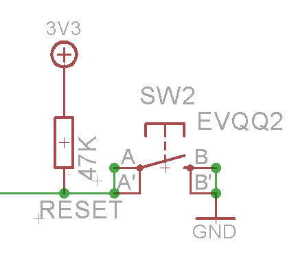
AVR Reset
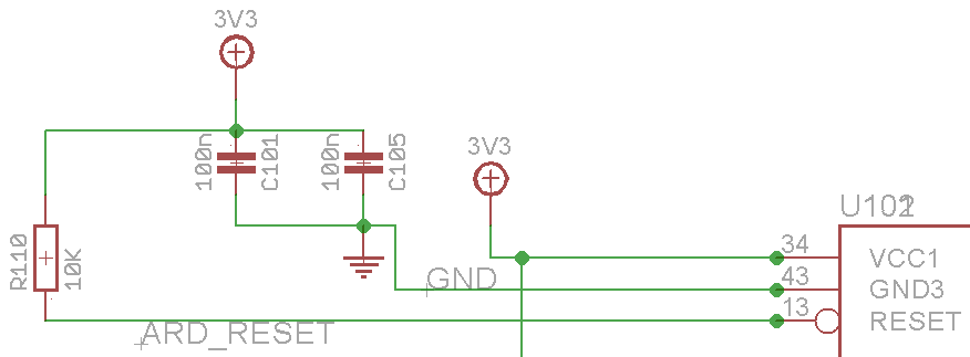
The AVR reset pin is connected to and under control of the FPGA (Pin139) so the running state of the AVR is dependent on the circuit you have loaded to the FPGA. The default configuration is to connect the AVR reset pin to the user switch (SW1) and invert it so that the AVR is running when SW1 is up and stopped when SW1 is down. But please note, not all FPGA circuits are setup that way, you will need to look at the schematic for the circuit you have loaded. For example, the default circuit that is loaded to the Papilio DUO when it ships directly connects the AVR reset to a pullup resistor so it is constantly running - the user switch has no effect.
The AVR reset is active low which means that the AVR is in a reset state when the reset line is low.
There is a physical 10K pullup resistor connected to the AVR reset line. If the FPGA pin that is connected to the AVR reset line is placed in a high-z state then the pullup resistor will cause the AVR reset line to be high and the AVR will run. When the FPGA is in a reset state all pins are in high-z so one way to force the AVR to run is to hold down the FPGA reset line.
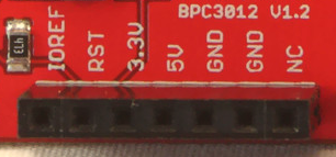
The AVR reset line is also connected to the RST pin of the Arduino Mega Header. This is the pin that is next to IOREF and 3.3V, near the Analog pins. If your FPGA circuit directly drives the AVR reset pin then it is a bad idea to also drive from this connection. If you want to use the RST header pin then you will need to place a pullup or pulldown resistor in your FPGA circuit on the reset pin (P139).
| Name | Direction (FPGA Perspective) | Function | Arduino Pin | Papilio Wing Pin | Papilio DUO Pin |
| AVR RESET | Input | AVR Reset | N/A | N/A | P139 |
User LED
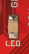
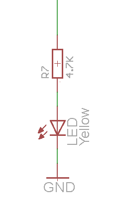
The Papilio DUO provides one user LED that is connected to pin 13, just like with the Arduino. The LED can be controlled by accessing pin 13 in your sketches or directly from the FPGA pin in your circuits.
| Name | Direction (FPGA Perspective) | Function | Arduino Pin | Papilio Wing Pin | Papilio DUO Pin |
| LED | Output | USER LED | 13 | N/A | P134 |
Links
License

Papilio DUO is licensed under a Creative Commons Attribution-ShareAlike 4.0 International License.
Papilio DUO copyright 2014 Jack Gassett, Gadget Factory.
Images
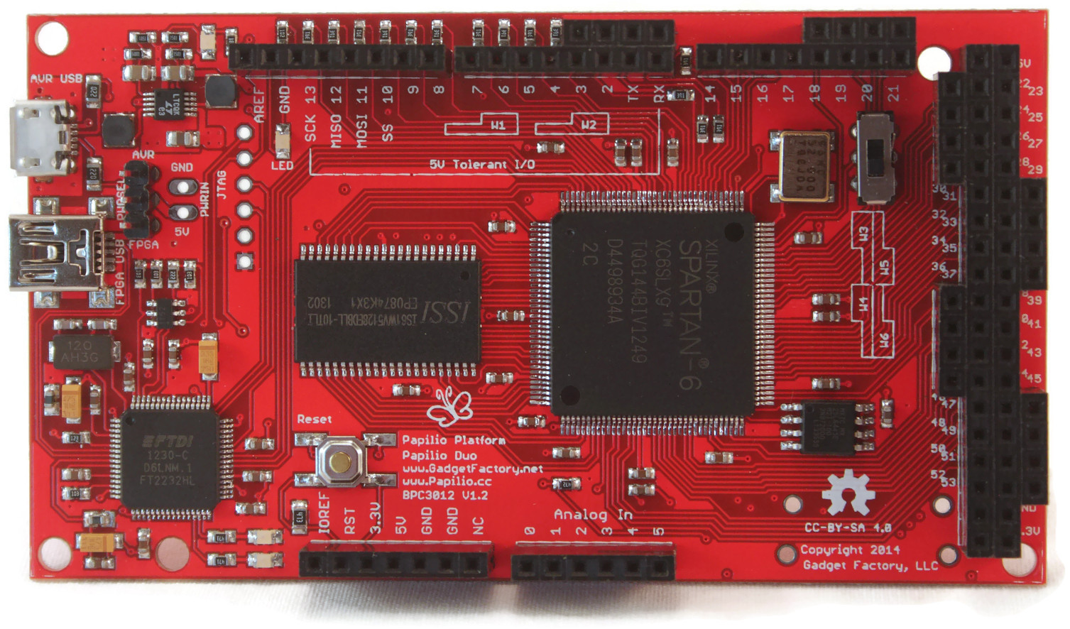
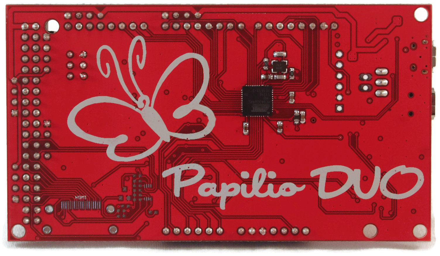
Papilio DUO
Click the images for full size hi-resolution views of the Papilio DUO.
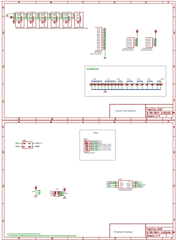
Papilio DUO Schematic
Click the image to load a PDF version of the Papilio DUO Schematic

Papilio DUO Pinouts
Click the image to load a PDF version of Papilio DUO pinouts diagram