
Hardware | Papilio DUO - Papilio One - Papilio Pro - MegaWings - Wings - Shields
Contents
Overview
Spartan 3E
Power
Dual Channel USB
SPI Flash
I/O
Oscillator
JTAG
LEDs
Links
License
Images
Papilio One
The Papilio is an Open Source FPGA development board based on the Xilinx Spartan 3E FPGA (datasheet). It has 48 I/O lines, dual channel USB, integrated JTAG programmer, 4 power supplies, and a power connector. It provides everything needed to start learning Digital Electronics.

Features
Power
- Four independent power rails at 5V, 3.3V, 2.5V, and 1.2V.
- Power supplied by a power connector or USB.
- DC Input Jack.
- Input Voltage (recommended): 6.5-10V
USB
- Two channel USB connection for JTAG and serial communications implemented with FT2232D.
- EEPROM memory to store configuration settings for FT2232 USB chip.
Spartan 3E FPGA
- 32MHz oscillator that can be used by Xilinx's DCM to generate any required clock speed.
- VTQFP-100 footprint that supports Xilinx XC3S100E, XC3S250E, and XC3S500E parts.
- I/O can be set to support 1.2V, 2.5V, or 3.3V.
SPI Flash
- 4M SPI Flash
Wings
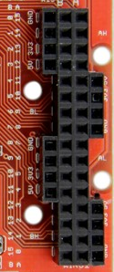
- 48 bidirectional I/O lines which can be split up as:
- 1x 32 Bit Wing or
- 3x 16 Bit Wings or
- 6x 8 Bit Wings
- .1" spacing for compatibility with bread boards.
Dimensions
- 2.7"x2.7"
Xilinx Spartan 3E

The Spartan 3E FPGA used in the Papilio One offers some exciting features:
Multi-Voltage
Digital Clock Manager (DCM)

FPGA Schematic
Multiple Signal Standards
Boot from SPI Flash
BRAM Memory Blocks
| Papilio Board | 18Kbit BRAM Blocks | Max SRAM | Usable SRAM |
| Papilio Pro | 32 | 576Kbit (72KByte) | 512Kbit (64KByte) |
| Papilio One 500K | 20 | 360Kbit (45KByte) | 320Kbit (40KByte) |
| Papilio One 250K | 12 | 216Kbit (27KByte) | 192Kbit (24KByte) |
BRAM's are 18Kbit in size including two parity bits. In most cases the two parity bits are not used so the BRAM's usable size becomes 16Kbit. If your design can use an 18 bit wide bus then it is possible to utilize the parity bits for data and gain access to all 18Kbit memory space.
Power

The Papilio One can be powered from the USB connector, an external power supply, or a battery. The PWRSELECT jumper controls whether the USB connector or the Power Jack/PWRIN connectors are active.
Power Selection

Power Schematic
Power Jack
- Input: 6-15V DC
- Current: Draws up to 800mA
- Size: 2.1mm
- Polarity: Positive Tip
RPAR
Dual Channel USB
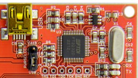
The Papilio One uses the FT2232 dual channel USB chip for JTAG programming and Serial UART communications.
- Channel A is connected to the JTAG pins of the Papilio One and provides very fast programming of the FPGA (500mS).
- Channel B is connected to the Papilio One in an Asynchronous serial UART configuration that is capable of speeds up to 2MHz.
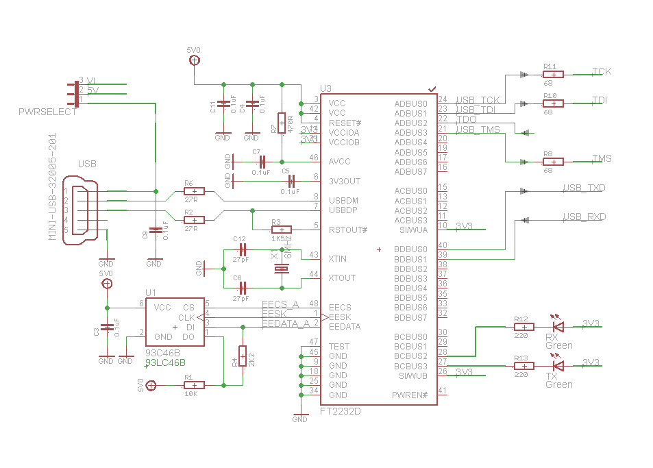
USB Schematic
| Name | Direction (FPGA Perspective) | Function | Arduino Pin | Papilio Wing Pin | Papilio One Pin |
| RX | Input | FPGA Serial Receive (MISO) | N/A | N/A | P88 |
| TX | Output | FPGA Serial Transmit (MOSI) | N/A | N/A | P90 |
SPI Flash

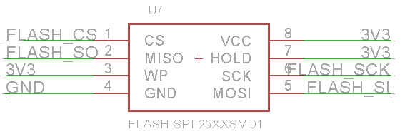
The 4Mbit SST SST25VF040B SPI Flash chip provides plenty of space for a boot bit file and user data. Any bit file written to SPI Flash using the Papilio Loader tool will automatically startup when power is applied.
| Name | Direction (FPGA Perspective) | Function | Arduino Pin | Papilio Wing Pin | Papilio One Pin |
| FLASH_CS | Output | SPI Flash Chip Select | N/A | N/A | P24 |
| FLASH_CLK | Output | SPI Flash Clock | N/A | N/A | P50 |
| FLASH_MOSI | Output | SPI Flash Master Out Slave In (MOSI) | N/A | N/A | P27 |
| FLASH_MISO | Input | SPI Flash Master In Slave Out (MISO) | N/A | N/A | P44 |
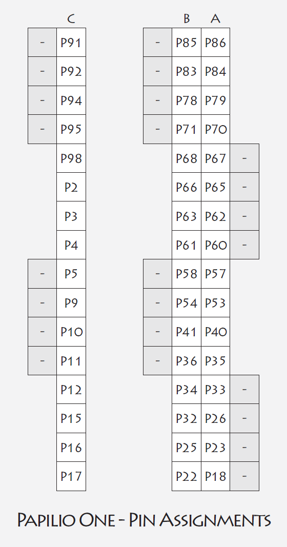
I/O
I/O Blocks
- Programmable pull-down, pull-up and float resistors (Pull-down by default on unused pins).
- Programmable input delay.
- Optional keeper circuit (keeps last logic level, see spartan-3E datasheet page 18).
- 2 to 16 mA programmable output current drive strength.
- All I/O pins are in high-impedance state during configuration (program loading). Unused pins are pull-down inputs by default with the Xilinx ISE software.
I/O Banks

Oscillator

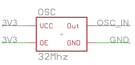
The Papilio One has a 32Mhz oscillator that can be converted to any speed desired inside the FPGA using the Digital Clock Manager (DCM). There are four Digital Clock Managers (DCM) available for your designs.
| Name | Direction (FPGA Perspective) | Function | Arduino Pin | Papilio Wing Pin | Papilio One Pin |
| CLK | Input | External 32Mhz Oscillator | N/A | N/A | P89 |
JTAG

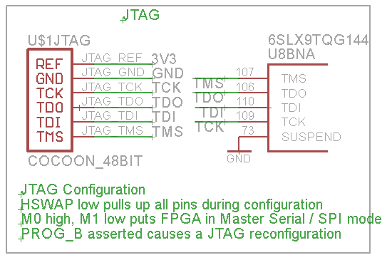
The JTAG header on the Papilio One is provided so external JTAG programmers can be used:
Use a Xilinx Programming Cable
| Name | Direction (FPGA Perspective) | Function | Arduino Pin | Papilio Wing Pin | Papilio One Pin |
| JTAG_TMS | Input | JTAG TMS | N/A | N/A | P75 |
| JTAG_TCK | Input | JTAG TCK | N/A | N/A | P77 |
| JTAG_SI | Input | JTAG SI | N/A | N/A | P100 |
| JTAG_SO | Output | JTAG SO | N/A | N/A | P76 |
LED's
The Papilio One has a power LED, a RX LED, and a TX LED. The power led lights up to indicate that power is being supplied to the board while the RX and TX led's show UART traffic.
Links
License

Papilio One is licensed under a Creative Commons Attribution-NonCommercial-ShareAlike 3.0 Unported License.
Papilio One copyright Jack Gassett, Gadget Factory.
Images


Papilio One
Click the images for full size hi-resolution views of the Papilio One.

Papilio Pro Schematic
Click the image to load a PDF version of the Papilio One Schematic